The Observatory is Operational 
Firstly I have solved two of the issues left over from the last stage.
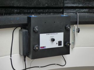 |
I have solved the problem of where to mount the transformer that drives the motor that revolves the dome. I stuck magnetic tape to it and that holds it on the side of the drive assembly. |
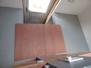 |
I found that I really needed to be able to stand on the west side of the pillar where the stairs come up. So I have a piece of 12-mm plywood, strengthened with battens screwed to the underside, which simply bridges the gap with the battens preventing it from slipping out of place. This works well but does prevent the use of the stairs. If I need to go down, I simply lift the board and lean it against the wall over the door, go down the stairs and duck under the board. |
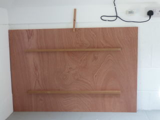 |
When not in use I store the board against the northern wall with a simple clip to ensure that it doesn't fall over.
The wire you can see in the background is the mains feed to the dome drive. It is longer than it needs to be but it was easier to fix it so than to cut it to length.
|
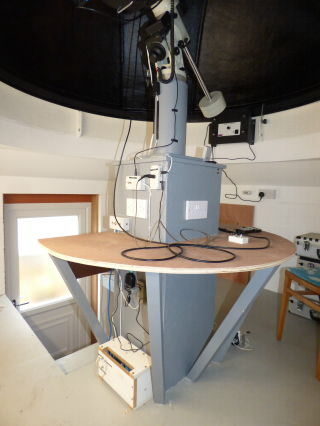
I have installed the low-voltage electrics. Almost everything runs off a 12-volt lead-acid battery which is housed on the ground floor* near the pillar. A single cable comes up through the first-floor platform goes to a centre-zero ammeter and thence to a control box just above the highest platform (which mainly acts as a desk but which is strong enough for me to stand on). This box is the same one that I used in my last observatory and enables me to connect the battery to either the charger, the equipment, or switch it off (details on the page linked above since when I have sourced a centre-zero, moving-coil meter).
*(Note to my American friends: What you call the first floor, we call the ground floor, and what you call the second floor we call the first floor, and so on up....)
|
Looking at the column from the south-east. I've put my distribution centre on the south side of the pillar. The twin mains outlet will probably not be used; below and to the left of these is the 12-volt control box; above them is the 12-volt distribution box with three sockets, and to the right is a box connected to the Meade focuser which runs off 18 volts. The battery charger and the 12-to-18-volt converter are housed below the desk and the latter uses the same connector I used previously. The focus controller uses the same circuity that I used before, but I have redesigned the implementation. I was never very happy with my last design so I have rebuilt it into a slightly larger box connected to the fixed box via a 4-way cable. This box is visible towards the right.
Move your mouse pointer over the picture to see these components labelled.
I have become concerned about cables hanging from the telescope, particularly from the camera end, so, where possible, I have attached all such cables to the central pillar and then, with a suitable loop, to the shelf. I will elaborate on this issue below. Two cables come from the rear of the OTA, the camera cable(s) and the feed to the focuser. The camera in the picture below is a firewire device and the cable is rather heavy and stiff. Fortunately I have a long one and I have routed it up to the dec axis before it comes down to the desk. I've tried to route the focuser cable similarly but it is a coiled cable and that makes it more difficult. However I have routed it to the box I used previously which is mounted on the pillar using double-sided sticky pads; (magnetic tape gave poor adhesion to the curved pillar).
|
Balancing
I have used fork mounts ever since I obtained my first modern telescope, and I am slowly getting used to the behaviour of a GEM. For example, I was imaging Saturn and was unhappy about my focus, so I found a nearby bright star to focus on. It was only a few degrees away from Saturn but on the other side of the meridian, so the mount swung my telescope over and slewed all the way to the other side just to move a few degrees. I had both the cable from the camera and that from the focuser hanging down so these got wound around the mount and there was a risk of their going tight. I also noticed that, when imaging Saturn the image was drifting upwards. I had my mount aligned to the pole as well as the polar-scope could manage, so it couldn't have been too far out. Also the image was wobbling in a way that initially I assumed was atmospheric turbulence, but somehow it didn't look quite like that. It hadn't done it on Jupiter earlier. Eventually I reckoned that two things were happening. (1) The load of the two cables pulling on the back of the OTA were causing the dec to slip slowly causing the drift, and some sort of vibration was going up the cables, wobbling the image. Whether the slippage is typical of this mount or if I have a defective one I don't know but the solution seemed to be better balance.
Balance in dec is an issue for me. I had balanced the 'scope pretty well when it had only an eyepiece fitted, but addition of the camera had unbalanced it significantly. Balancing in dec is supposed to be done by sliding the OTA along its dovetail fitting. This means loosening the heavy OTA and wherever I put it there is the danger of it falling off. I'm likely to have to do that more than once at night. I'm not happy with that idea. I have a dovetail clamp that I bought to support a guide 'scope and some lead sheet left over from my building works, so I cut four pieces to size and bolted them onto the clamp. I can now slide this up or down the OTA's dovetail bar to effect balance. In this way I was able to balance out the fairly small camera and a barlow lens as shown in the first picture below.
|
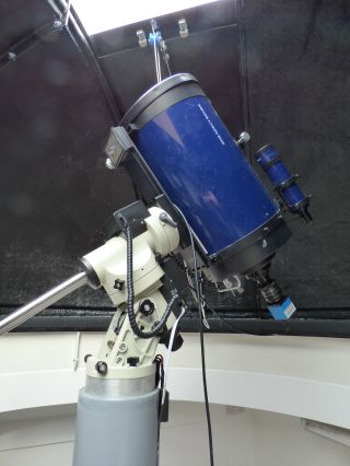
Here is a picture of my LX200 with arrangements I have made to try to keep it balanced. The camera is a DFK 21AF04 which only weighs 231 g, and also attached is my X2 adaptor lens which weighs 356 g. The extra counterbalance weight can be seen at the top of the dovetail bar underneath the telescope. I may need to add more lead because I have at least two heavier cameras. I have a second dovetail bar on the top of the OTA to which I can attach further weight if necessary; and indeed there is a dovetail clamp up there which is just visible.
|
|
|
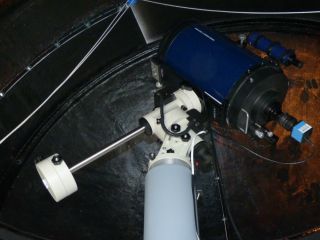
Finally I am becoming concerned by the RA balance. Thanks to a member of the local Astronomical Society who lives near me, I knew that I would need the longer balance bar in order to balance the LX200. By the time I had the camera and its extra balance weights, I had to move my two RA-balance weights right to the end of the bar. If I want to add a guide 'scope, I'll need to extend the bar even further or add an extra 2-kg weight. I can extend the bar quite easily (the original bar will screw into the end of the extended bar) but it will become more hazardous as it moves.
I finally decided to purchase another 5-kg weight hoping that it would enable me to use the shorter balance bar. Unfortunately this did not prove to be the case but I do now have the flexibility to add heavier cameras and a guide 'scope.
|
First Light Photos
All these pictures were taken on 9 June 2015. Considering how low these planets are in the sky and the fact that it never gets dark here at this time of year, I am very pleased with these results.
 |
 |
 |
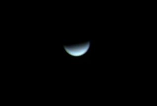
| Venus, taken at 20:58 UT when Venus was at an altitude of 20° 20'. Taken with a DFK 21AF04 camera at prime focus of my LX200. The planet subtended an angle of 24 arcsec. |
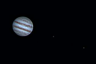
Jupiter, taken at 21:06 UT when Jupiter was at an altitude of 23° 15' and was only just visible over the roof of my house. Two of the Galilean satellites are visible. The one nearer the planet is Europa and the other one is Io.
Taken with a DFK 21AF04 camera at prime focus of my LX200. Jupiter subtended an angle of 33 arcsec. |
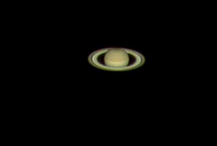
Saturn taken at 22:49 UT when Saturn was at an altitude of 18° 24'. Taken with a DFK 21AF04 and X2 adaptor lens on my LX200. I have reduced the image by 50% to make the scale the same as the other two images. The planet subtended an angle of 18 arcsec. |
My centre-zero, moving-coil meter
|
Discharging. The mount was in tracking made and you can see it was drawing about 0.7 amp. |
|
Charging. The battery can charge at 5 amps but it is nearly charged here and the charging current has started to fall. When fully charged, of course, the current falls to zero. |
| | Return |
Home
Back to Equipment