
Focusing the LX200 with the keypad is more difficult than it need be. Firstly, it is a two-handed operation because two buttons have to be held down simultaneously. Secondly, if one has just done a goto, the Mode button must be pressed before the focuser can be accessed. Thirdly, there is considerable inertia in the motor which causes the focus to continue changing after power is removed. To get over these problems I decided to make another controller. In some ways I have followed Jan Timmermans' design and in others that of Bob Macgregor.3. Controller for the Electric Focuser.
The features I wanted were:
(a) No overshoot when the power is cut;
(b) One-handed operation;
(c) Easy to see the direction of adjustment.
(d) 18-volt operation for full speed of adjustment.
The first requirement prevented the use of a centre-off switch, as used by Jan Timmermans, because to stop the motor as soon as power is removed, it is necessary to short out the motor contacts. So I needed to use a single-pole double-throw switch. By using a biased switch, as soon as I release pressure, it springs back and switches the feed from power to a short circuit. So I had to provide a second switch to reverse the polarity. Although I needed variable speeds, I didn't think I needed infinite resolution and I decided that a simple switch would be easier to operate one-handed than a variable (as used by both my inspirations).
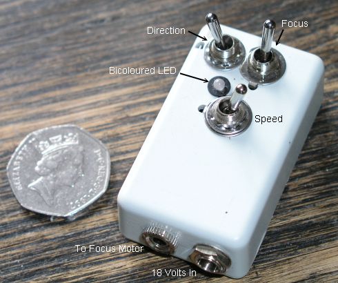
Here is the final box. I chose the smallest box I thought would do, but I overlooked the room taken up internally by the studs that accept the screws which hold the lid on. If I were to do this again, I would choose a slightly larger box. All the switches are miniature toggle switches. I would have preferred a push button for the focus switch, but I could not source a change-over version. To give a better idea of size, the coin is a British 50p coin which is 27 mm in diameter.
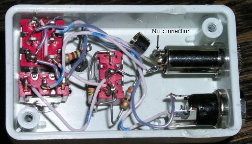
Here is the inside of the box. You can see it is a bit crowded. It is very important that no connection be made to the terminal that connects to the middle contact on the plug. In the plug (or at the motor) this contact it connected to the outer contact; if it is connected to the same terminal in the socket, there is a danger of short-circuit if the plug is not inserted fully or (unlikely I admit) the plug is inserted or removed whilst focusing.
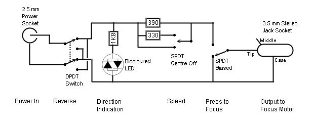
This is the circuit diagram. It is powered from 18 volts, derived from the battery pack I use to power the telescope. By experiment I found that a series resistor of about 400 ohms was the maximum that allowed the motor to start up. This value is selected when the switch is in its centre, off position. In the up position (in the diagram) a second resistor of 330 ohms is switched in parallel to the 390-ohm resistor giving a combination of 180 ohms which gives an intermediate speed. In the down position, the resistor is shorted out and I get full speed. The 1800-ohm resistor limits the current through the LED.