
In the diagrams below, lines that cross do not connect unless there is a large dot at the intersection.
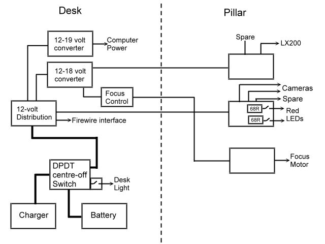
Although I have mains electricity laid on to the observatory, it normally will be off at night (it is tapped off the supply to the pump in my pond). Before I built the observatory, I powered everything off a 12-volt lead-acid battery and I saw no reason not to continue doing so. This is the general wiring diagram.
Apart from the DPDT-switch box all the boxes are simply distribution boxes and, in general, the input is wired in directly and the outputs are 2.5-mm power connectors (the exception is the 18-volt box on the pillar which I took from the tripod and which was fitted with three sockets).
The LEDs on the pillar will be sited on either the pillar or the telescope to illuminate the scales. I may wire these together in which case I have a spare which I may use to illuminate the camera position.
19th November 2009
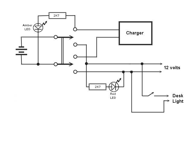
The DPDT-switch Box
The battery is wired to the common contacts of a double-pole, double-throw, centre-off switch. This enables me to isolate the battery completely or to connect it either to the charger or to the various components that need power. The box carries two LEDs, a red one lit when the load is connected, and an amber one lit when the charger is connected. It also carries a switch and a socket to supply the desk light, which is an LED cluster. This is the wiring diagram.
19th November 2009
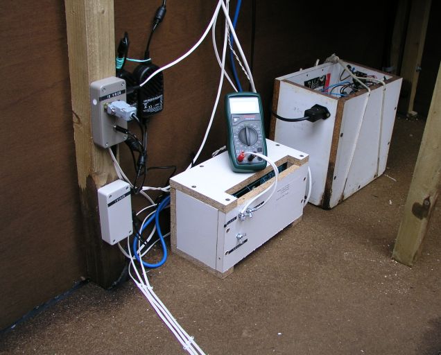
This is the assembly under the desk. The battery is in its wooden box at the back; the power comes in and out through a Euro connector on the end and is protected by a fuse. In front of it is the charger; this is a power pack from an old instrument with voltage stabilization and current limiting. The battery needs this type of charger. The two distribution boxes are screwed to the vertical post. The two DC converters don't have any way to screw them to anything, so are stuck to the outside wall with "Sticky Fixers"*. Three twin cables run across the floor and are pinned down to prevent a trip hazard. (There will be a fourth as I want to extend the hand controller for the LX200, but I am having difficulties sourcing the necessary connectors.) The electronic multimeter monitors the charging current from the charger. I would like to replace this with a much more convenient moving-coil meter but they don't seem to make them any more so I will have to try to adapt an old milli-ammeter that I have.
*Double-sided sticky pads.
20th November 2009
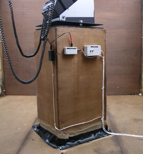
The pillar side of the assembly consists of the three boxes, one each for 12 and 18 volts, and one for the focuser to plug in.
20th November 2009
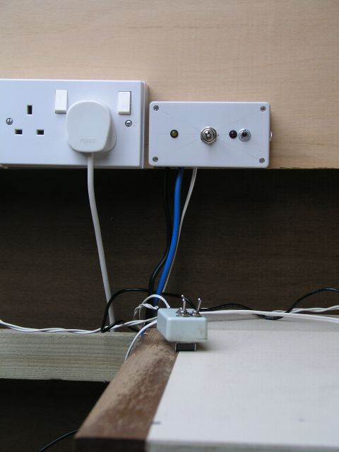
The main 12-volt switch is mounted on the backboard next to the mains sockets into one of which the charger plugs. My little focuser control can be seen in the foreground; it is backed by a magnet which was very useful at the tripod so that I could stick it to a leg, but is redundant now.
20th November 2009