
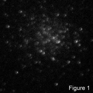
 In January 2015 I purchased an ex-demo Revelation Ritchey-Chrétien OTA. Owing to the building of my new observatory, I was unable to use it for several months. When I finally tried it out it was immediately apparent that it was seriously out of collimation (see Figure 1 to the right). I had some experience of collimating a cassegrain telescope with my LX200, so I set to to try to collimate this RC telescope. Having little success I contacted the supplier who was helpful and sent me instructions from Orion and a link to instructions from Astro-Tech. I am assured that almost all, if not all, RC OTAs are made by the same Taiwanese manufacturer so they are effectively identical. They also pointed me to the first of a set of three videos by Stephen Kirk which describe the collimation of an RC telescope in great detail.
All these sources started by stating that the telescope had been collimated by the manufacturer and only very small adjustments would be necessary. If that was true with my OTA, something nasty had happened in its life prior to its coming to me. They also stated that the cross-head screw behind the secondary mirror should not be adjusted as its function is to hold the secondary onto the supporting structure. Before I read this, I had examined this screw and found it to be loose and tightened it. This one act improved the collimation from dreadful to poor. However by then I had altered any settings left by the manufacturer. In addition the supplier made it apparent that I'd had all the support in this area that I was going to get, so I was on my own. I realised I had to start from scratch.
Both the Orion and the Astro-Tech methods relied on a Cheshire eyepiece; the method by Stephen Kirk used a very expensive laser collimator. I couldn't really see the advantages of the laser collimator that warranted its considerable extra cost, so I decided to settle for a good Cheshire eyepiece. In retrospect it may have been a little too good in that it has cross wires and a cross on the mirror which are useful for collimating Newtonians, but which were somewhat in the way for this telescope. However it served its purpose admirably.
The purpose of collimation is to ensure that all the components in the telescope from the primary mirror to the eyepiece (or camera) are on a single line called the optical axis. In addition, the focal points of all optical elements must also be on that optical axis, which involves tilting the component until it is normal to that axis. In a folded design, such as the RC, there are two mirrors and an eyepiece involved. The optical axis is defined by the line between the centre of the primary mirror and the centre of the assembly which holds the secondary mirror. This line is defined by the design and construction of the telescope. In addition the tilt of the primary mirror is built in by the manufacturer and there are no user-accesible adjustments for it. (This statement, and the one that follow, may not be true; see Note 1 below.) If you have a serious concern that the primary mirror is out of position, you should contact the supplier with a view to returning it to the manufacturer for recollimation. In the present design the usual adjustments can be made to the orientation of the secondary mirror, and the alignment of the exit tube, which carries the eyepiece, can also be adjusted to bring the eyepiece onto the optical axis.
I should emphasise that what follows is the way I did it and carries no more authority than that. I differ from other descriptions in a number of ways, but I was collimating from the start and not making minor adjustments to a well-collimated system.
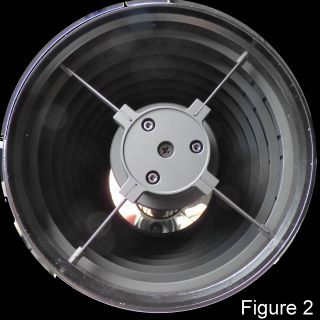 The very first thing to do is check the cross-head screw in the centre of the secondary-mirror housing at the front of the telescope (see Figure 2) and make sure it is tight. This was the source of all my problems because it was loose. Don't over-tighten it; just nicely firm will do.
Since the secondary is aligned by looking through the Cheshire collimator fitted into the eyepiece holder, it seems to me the next thing to do is to align the eyepiece holder (see Note 1 below). I did this with only the focuser attached. There is an argument that the collimation would be more accurate if all the extension rings were included. I was doing this inside my dome and space was severely limited by the dome, but if you are doing this outside or in more spacious surroundings, you may prefer to put all the extension rings on.
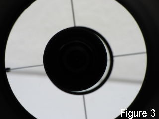 Put the OTA roughly horizontal and pointing at a bright surface (take the cover off), stand back from the telescope and look into the 1.25-inch opening at the rear with one eye. You will see a bright circle surrounding a dark centre. Adjust the position of your eye in three dimensions until the bright circle just fills the aperture at the exit from the focuser. If the rear aperture needs adjusting you will see something like Figure 3. (In this and Figure 5, ignore the grey line running across the picture. I was pointing the telescope at the white wall of my observatory and that line is on the wall.)
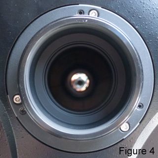 The adjustment is made by using the three pairs of screws you can see in Figure 4. Each pair consists of a larger bright, shiny screw and a smaller black screw, each adjusted by an Allen key (hex wrench); 3 mm for the shiny screw and 2.5 mm for the black one. Other descriptions say that the shiny screws pull and the black screws push. My own impression is that the bright screws are the adjusting screws and the black screws are the locking screws (which certainly push on something). Since mine was badly off, I loosened all the black screws and adjusted with the shiny ones until the view in the back looked like Figure 5.
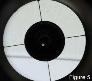 This is a typical 3-point adjustment and it is best you discover for yourself which way the image moves when you tighten any screw. You will soon get the hang of it. I then tightened the black screws evenly and gently, watching the alignment as I did so. As the black screws tightened there was some slight movement so I continued the tightening by unscrewing the corresponding bright screw.
You are now in a position to adjust the secondary mirror using the Cheshire collimator. You can see a picture of this here, but it consists of a tube, which fits into the 1.25-inch eyepiece holder, which contains a 45° mirror opposite a large aperture in the side of the unit. It is closed off at the back but has there a small hole which lines up with a similar hole in the centre of the mirror. In use you arrange for light to enter the large aperture at the side—I used a torch but it was a bit tricky, if you are outside just use the sky. This light is reflected down the optical tube to the secondary mirror where it is reflected back to the eyepiece.
When you look through the small hole at the back of the collimator you will see a small black dot which should be centred in a small black circle. (I am not clear if the small circle is pained on the secondary mirror or is a reflection of something, but I think it is on the mirror.) If the dot is not centred in the ring, then the three adjusting bolts on the secondary mirror (Figure 2) have to be adjusted until it is. You need a 4mm Allen key for this and it is wise to have the telescope pointing downwards when you do it so that, if you drop the key, it doesn't fall down the tube and hit the primary mirror. If later you do a final tweak on a star, I would advise you to tie a piece of string to the key and loop it round your wrist, just in case you drop it. There are no locking screws as such up here, so adjust the screws together by very small amounts. Loosen one screw and tighten the other two or loosen two and tighten the third, so that you always end up with all three screws tight. As before, you will learn by experience which way the image moves when you tighten a given screw. Make only small adjustments (never more than a quarter of a turn) at a time.
When you have finished these adjustments, your RC is collimated. How well depends on how well you have been able to do the various adjustments. The final test is a star test. On a clear night with steady seeing look at a bright star. Defocus the star slightly first in one direction and then in the other. What you hope to see is a tiny dot surrounded by a bright ring with the dot exactly in the centre of the ring. If the dot is not central, adjust the secondary until it is. The problem with this test is the condition that you have "steady seeing". Where I am (and was until recently) I don't believe I ever had steady seeing. Certainly when I checked my collimation I saw a dancing ring with little sign of the dot. Putting on a camera and taking a video, I stacked 84 of the resulting pictures and obtained the image show in Figure 6. Perhaps not quite perfect, but, considering the seeing conditions, probably good enough.

Finally here is another picture of M13 taken after these collimation procedures. Like the picture in Figure 1, it is a single frame from a sequence and trimmed as the first one was. The final picture after stacking 56 images and some minor enhancement is shown here.
Note 1.
I have since been told that the eyepiece holder is rigidly fixed to the primary mirror and that the adjusting screws align the primary mirror. I don't believe this makes any difference to the need to align this, but some people add an extra device at the back to enable the holder to be adjusted independently of the mirror. I am, for now, assuming that this is not really necessary but may be for absolutely accurate collimation.