
In 2005 I purchased a second-hand Sky-Watcher ST80 with a view to using it for wide-angle pictures and for guiding my LX200. For both these applications I needed to mount the new telescope on my LX200. Below are a few pictures to show how I did it. My work tends to be a bit rough and ready but functional.. With guiding in mind, I wanted the mount to be as rigid as possible but also not too heavy. I only have normal wood-working tools, so wood was my natural material.. Ideas came from several other members of QCUIAG - my thanks to them. The main piggyback is made from laminated chip-board; this may not be the best material but I had some recovered from shelves and the like. It is rigid and not too heavy.
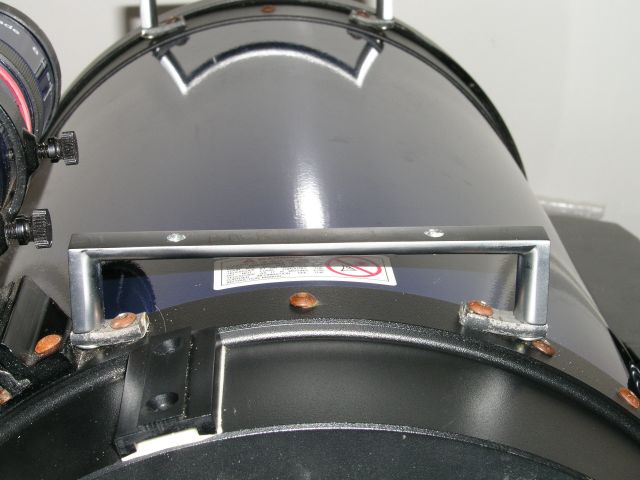 |
The first problem was "how to fix it to the telescope?". Following an idea from Jan Timmermans, I tried to find suitable drawer handles in our local B&Q (perhaps Britain's biggest DIY store), but could find nothing suitable that was designed to screw from the front of the drawer, but I did find these simple but substantial handles designed to be screwed through from inside the drawer. How to fix them to the telescope? I found some iron bar which seemed soft enough that I could bend it, but substantial enough not to bend under the load. (I've no idea exactly what it is but it does rust slowly.) I cut short lengths of this material, bent it roughly into shape, and drilled two holes. This picture shows the assembly in place at the rear of the telescope; (the front one is visible as a nice reflection in the telescope itself). |
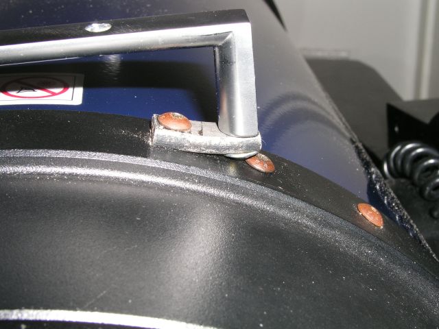 |
Here is a closer view of this fixing arrangement. The two handles could be made parallel by packing under the handle with washers as necessary. |
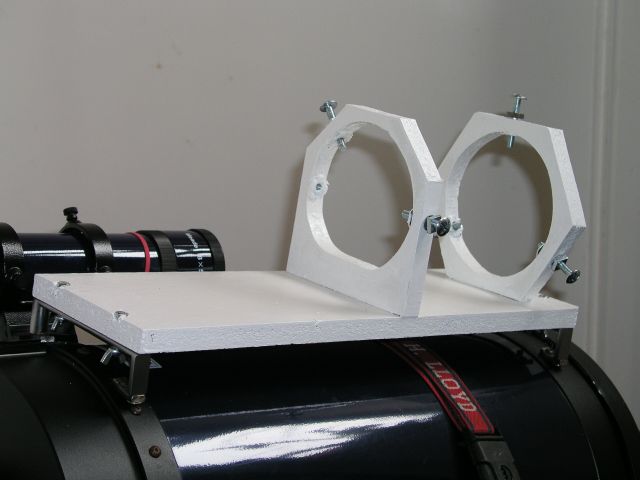 |
Then I cut a piece of chip-board to fit across the handles and held by bolts running through it and holes drilled in the handle. This raised another question - nuts on top or underneath? If on top, the bolts would be loose (but could not fall out) and putting the assembly in place was quite difficult as the bolts wouldn't stay in place. So I decided to put the nuts underneath as that made putting the assembly onto the 'scope much easier. However attaching the nuts is a lot more difficult in the dark with cold fingers than it is inside in the light and warmth. In practice all four are not really necessary. This board carries two support rings, one hexagonal and one sort of hemi-octagonal. The reason for this is that, for guiding purposes, I wanted some latitude for adjustment of the piggy-backed 'scope relative the main 'scope and I wanted to make such adjustments as easy as possible. Further details below. |
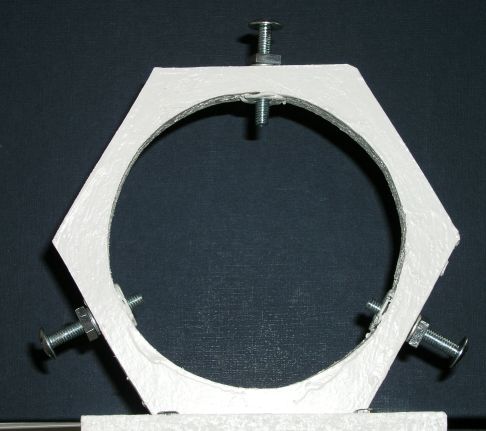 |
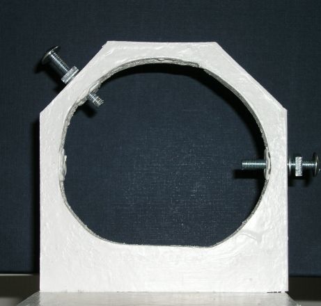
This is the front support and is a conventional hexagonal "ring" with the usual three fixing bolts. The significant point is that one of these bolts is at the top. This means that if I loosen this bolt and adjust the other two together, the 'scope moves vertically (roughly anyway!). The bolts are held by a Tee Nut, which is a nut designed to be firmly fixed into wood and I have used them before on the azimuth adjustment of my wedge. In this case I didn't use the spikes designed to drive into the wood, as the wood was not thick enough to take them, and chipboard splits rather easily. I bent the spikes flat with the nut and glued the nut in place. The square nuts on the outside of the ring are locking nuts. |
 |
And this is the rear support. This one is designed to move the 'scope horizontally. The 'scope itself rests on a flat section of the inner ring and can be moved by the screw on the right. There is provision for a second screw on the left, but I haven't installed that one as I think adjustment might be easier without it. The screw in the upper left then secures the 'scope in place against the wooden base and the horizontal set screw. I don't yet know just how much adjustment this will give me nor how well it will work in practice. Another little problem I haven't solved is how to protect the 'scope from being scratched by the fixing bolts without introducing flexibility. A (not The!) previous owner had not bothered so the 'scope is already scratched and, to be honest, a few scratches don't bother me much either; so long as I am gentle with the screws it should be all right, but I may try adding cycle puncture-repair rubber on the 'scope itself to protect it. |
 |
And here it is with the telescope and my Toucam attached. I was surprised how far behind the 'scope the camera has to be mounted. My next problem is the counter-weight. See below. Finally, I shall make individual boards to hold different assemblies, such as my modified Vesta or Toucam connected to SLR lenses. Will they need their own counter-balance boards? Probably. |
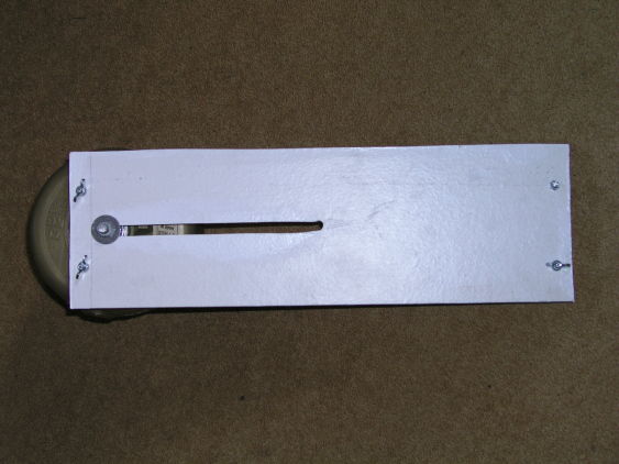 |
The counter weight is very simple. I cut a board to fit the same systems of handles as I used for the main platform, and cut a slot down the middle to give fore-aft adjustment. Through this slot runs a threaded rod, secured by two nuts and large washers. As it happened the weights have to be as far back as possible. Indeed I had to make the final adjustment by sliding the telescope back slightly. |
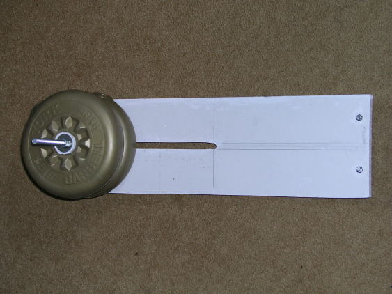 |
The weights themselves are 1.1 Kg training weights. Originally I used a single 2-Kg weight but its centre hole was a fraction smaller than the 1-Kg weights. The latter took circles of wood, cut with a hole saw, perfectly and are slightly conical so that the wood jambs in place. The weights also are just a little heavier, so could be close to the board, which also makes the whole assembly more compact. Maybe I shall remove the extra rod one day, but it is quite handy as a handle when the assembly is not on the telescope. Both the weights and the rod clear the base of the fork arms so that the telescope is still free to rotate. |
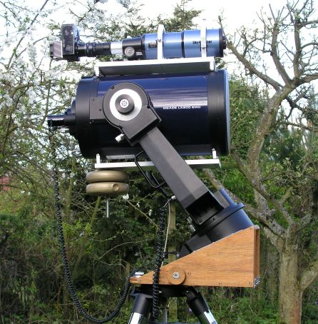 |
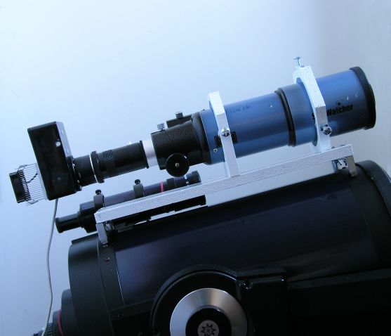
Now the whole thing attached to the LX200. The piggybacked 'scope is my ST80 with my modified Toucam 840K attached. The LX200 is mounted on my home-made wedge. This is my normal observing position facing east. As you can see my views to the east are somewhat restricted, but from here I get good views to the south-east and south. I have another site which gives me a better view to the south-west. |
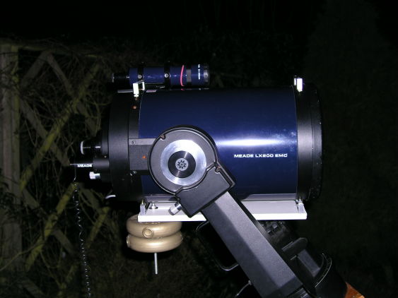 |
And finally a very strange observation. One night I put the balance weight on first and, when I rotated the 'scope to put the weight below it, this is where it balanced. I promise that, when this picture was taken, the dec lock was completely loose. I know there is no diagonal or eye-piece there and the lens cap is in place, but that is a 2.2-Kg weight hanging there, and it balances with the OTA horizontal. I was amazed! |