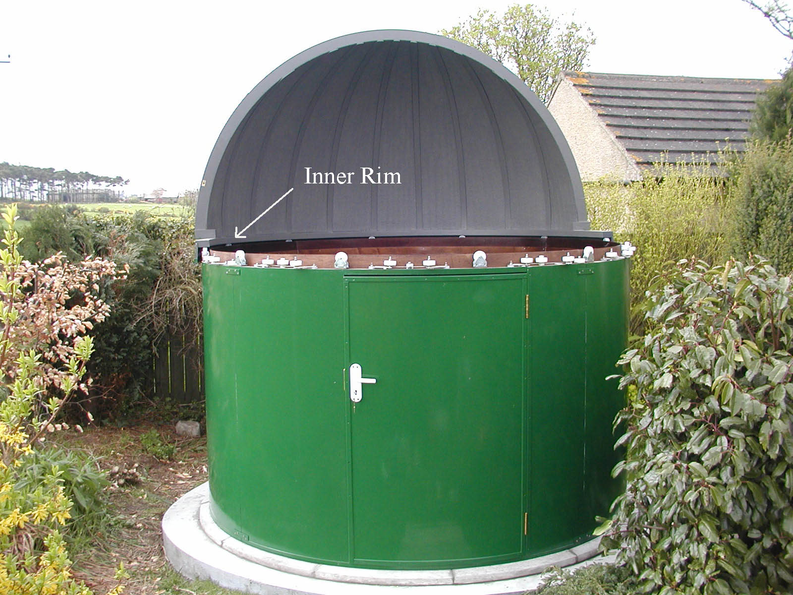
The Rigel system uses rubber rollers pinching an inner extended rim of the Pulsar dome. But my dome has a solid wooden rim as shown here in this photo from the original installation. As always click on the thumbnail for a larger photo.
Please note, some of the links will open in a new page - I use frames, and some links don't work directly.
As the result of a conversation on the UKAI imaging group, I decided to have a go at fitting some form of drive unit to my Observatory. Particularly when imaging with the 10" telescope (and even more so with my previous 12" one) I have to move the dome round every 30 to 40 minutes to keep the slot in line with the telescope. As I usually monitor the imaging progress from my computer in the house (using TeamViewer) this was a bit of an onerous duty, particularly in very cold weather, and occasionally overlooked with potential loss of images.
Because of the way the dome is constructed, the readily available units such as the Rigel system from Pulsar Observatories were not suitable. And quite expensive bearing in mind that mine is now 13 years old and feeling its age a bit, so perhaps not worth spending a lot of ££s!
Suggestions and encouragement from Chris Bailey on the UKAI group steered me in a suitable direction - many thanks, Chris.
|
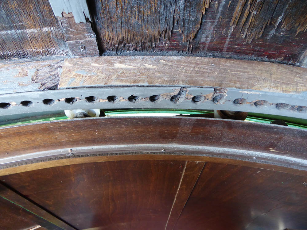
The Rigel system uses rubber rollers pinching an inner extended rim of the Pulsar dome. But my dome has a solid wooden rim as shown here in this photo from the original installation. As always click on the thumbnail for a larger photo. |
|
Chris mentioned using a windscreen wiper motor to drive the dome, and I came across two possible methods, one using a toothed belt fixed to the rim, the other using an 'Acorn Wheel'. Because my dome needs quite a shove to move it, I considered that the toothed belt might be prone to jumping. Lubrication of the bearing wheels helped to ease that a bit, but a long enough belt was going to be pricey, so I decided on the acorn wheel approach. Here is a system using that method . The commercially available wheel and strip from Explora-dome again was quite expensive, and I was also concerned that a windscreen wiper motor might not have sufficient power at low speeds to drive even the 6" wheel.
But again my browsing turned up this link which gave me the idea to use a toothed belt to reduce the speed of the wiper motor which ran at almost 100 RPM at full no load speed - far too fast as you will have seen in the acorn drive video above.
|
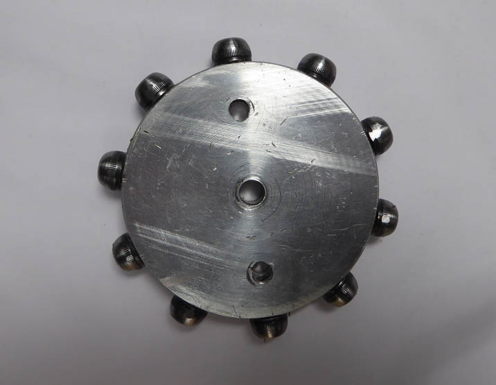
So in the end I decided to use an acorn wheel driving holes drilled in the rim of the dome. I had various bits of Aluminium bar and section already available. And fortunately have a small lathe. So the first thing was to make an acorn wheel. I used a section of round bar, 3 1/4" (82.5 mm) in diameter, with 10 socket head bolts rounded off and spaced equally around the rim. This is the finished wheel. I used 8 mm bolts, and made a lathe tool to round off the heads identically. |
 |
The motor speed needed to be controllable, and to obtain the very slow near sidereal speed would only be pulsed for a few seconds every 10 minutes or so. Electronic bits were needed for that, and were readily available. This is the speed controller, and this the interval timer. Both remarkably good value and available from various sources on eBay. I'll keep an eye on the links and correct them if necessary!
|
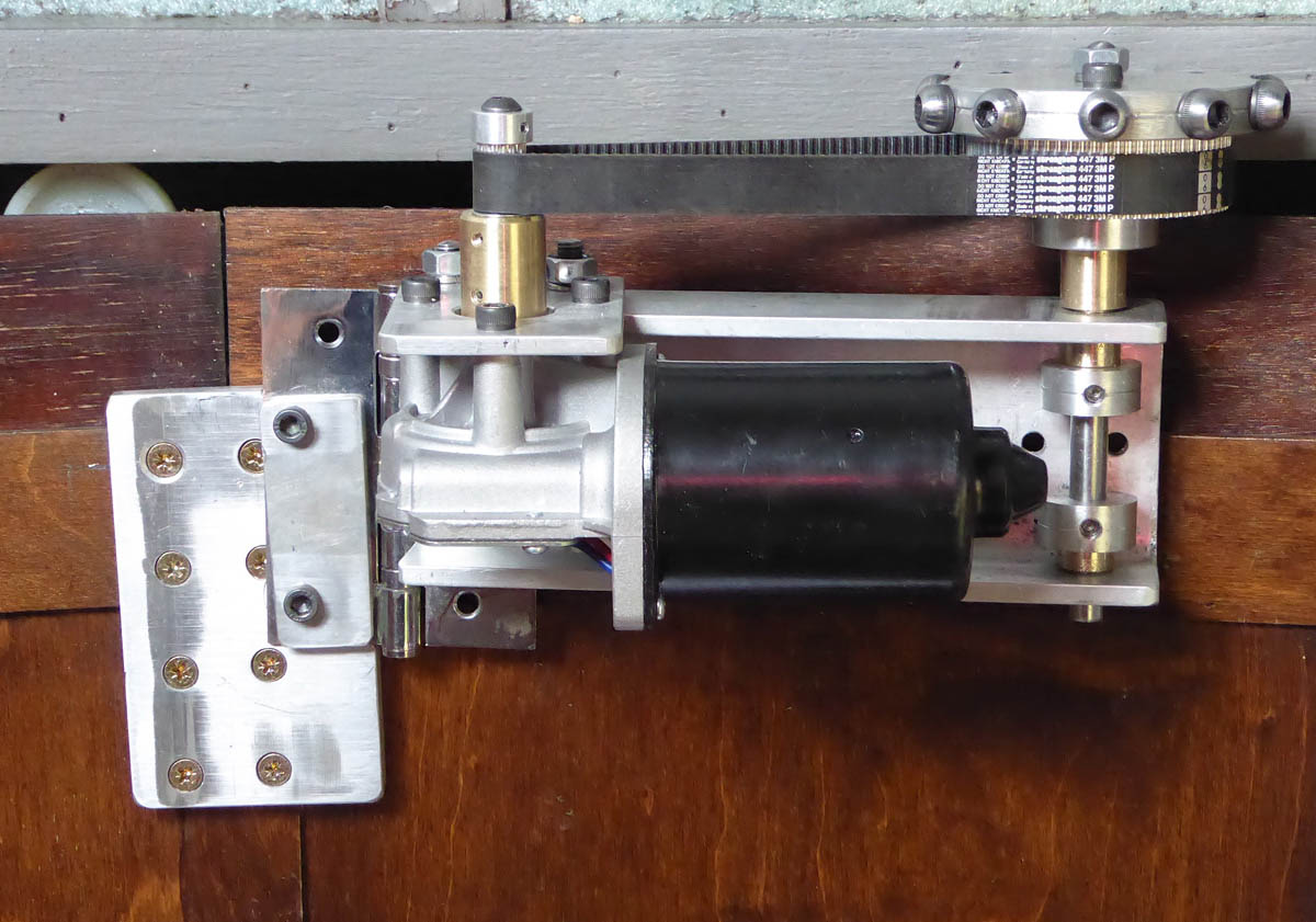
Then the work really started. Drive pulleys and belt sizes researched, ordered and delivered from Belting on Line - a very comprehensive site and excellent service. Much head scratching, but eventually arrived at this assembly, fitted to the dome wall. Still needed holes drilling and some form of tensioning. The toothed belt ratio is 14 to 72 teeth i.e. 5.14:1. The driven wheels are held on their shaft by stepping the shaft with a nut on top, so although the shaft rotates in its bushes, it's not actually doing any driving. For anyone working with toothed belts, there is a handy belt length calculator here. The pulleys and belt I eventually used (Belting on Line references) are: 1 x 14 Tooth HTD3 Pulley (14-3M-15F) (HP14-3M-15F) What looks like a bush between the driven wheel and the frame is actually a spacer with a very small clearance. Just there in case the lower shaft collar slips. The brass bushes for the main shaft are pressed into the frame. But if they slacken and start to turn in future I'll use grub screws to fix them. Slightly confusing in the photo, but the acorn wheel and large toothed wheel are bolted together - one of the two bolt heads is directly in front of the shaft nut in the photo. The motor mounting plate has a slotted hole for the bolt nearest the main wheel, for belt tensioning, and the hinge holes under the clamping plate are enlarged to enable final adjustments for level and height. |
 |
|
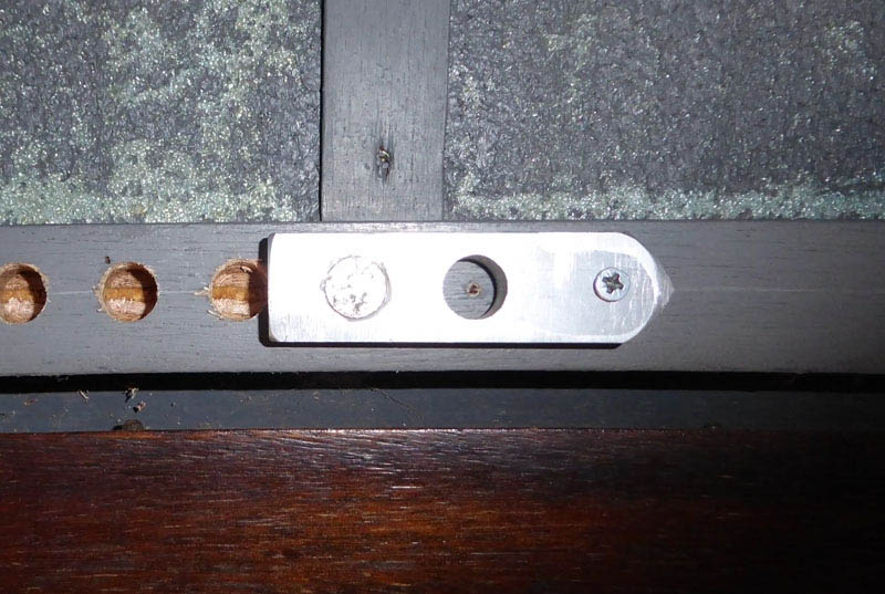
The next job was to drill the holes.They had to be a workable size with the spacing exact and consistent. After some experimentation on scrap bits of wood, I arrived at a suitable drill size and spacing, and made a jig to keep the spacing correct. To maintain the correct height on the rim I fixed a scriber (bolt with head cut off and turned to a point) in place of one of the domed bolts and pushed the dome round by hand with the point touching the dome rim. This left a clearly visible line. It also showed up some weakness at part of the rim due to wet rot, but a liberal application of wood hardener seems to have sufficiently strengthened that area. Once the first hole was drilled the round pin which fits the hole tightly was pushed in (you can see the back of it) and the point of the jig lined up with the scribed line. The Aluminium jig wore excessively after about 100 holes, so I had to remake it twice! |
 |
|
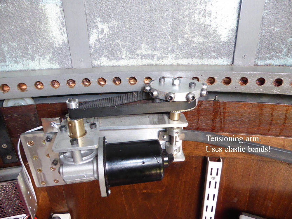
So with all the 264 holes drilled (I did an initial test with a smaller number!) I was able to run the drive in earnest. And I'm pleased to say all was well! This is a close up of the drive in running position, and a video here (5.75MB mp4). The creaking noise is just that - the wooden dome flexing a bit as it rotates. Nowhere near as bad as it sounds in the video. The motor runs faster in reverse than forward - just a feature of the motor, probably slight misalignment of the brushes, but nothing I can do about it, and not a problem. At maximum forward speed the dome does a full revolution in about 1 3/4 minutes, a bit faster in reverse. |
 |
|
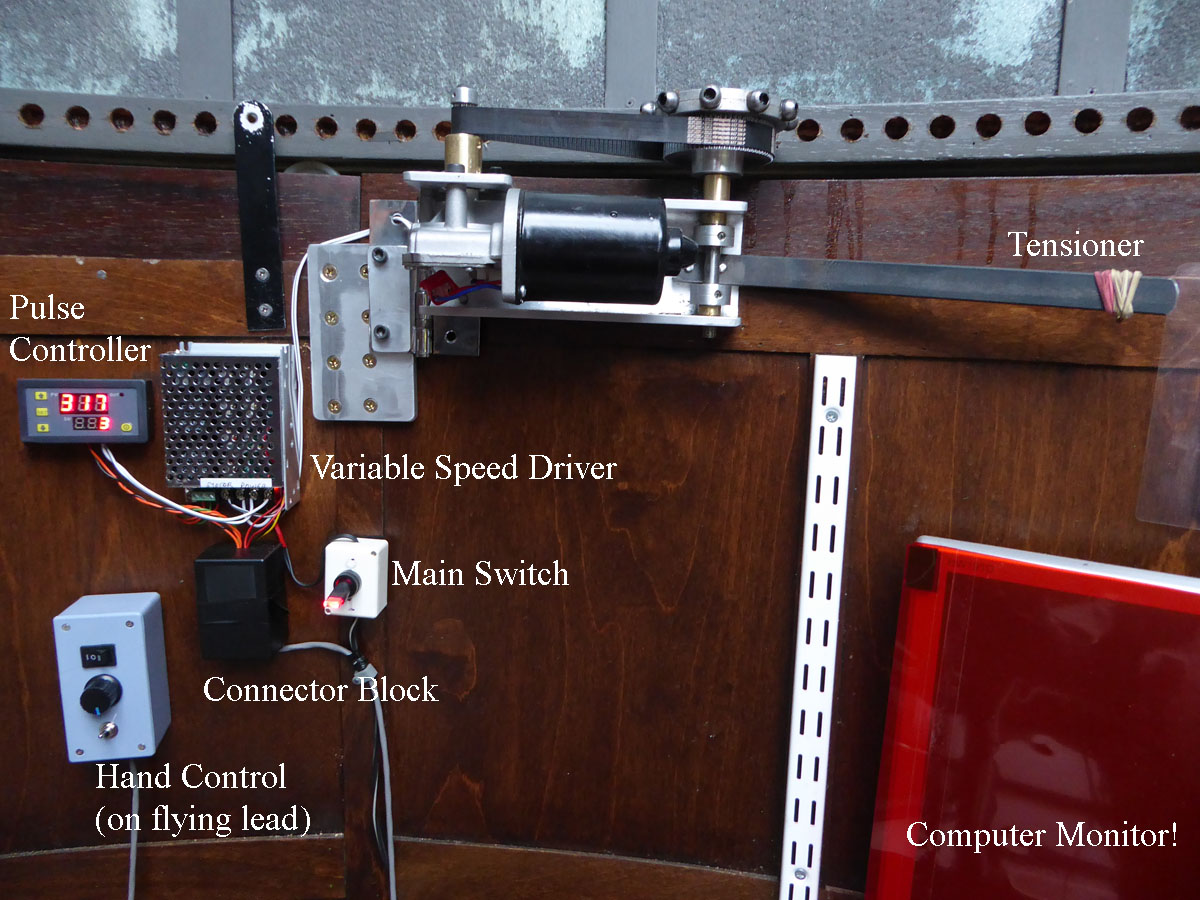
When I first made the remote control box there were just three controls on it. Forward/stop/reverse with the rocker switch, speed with the potentiometer and manual/automatic with the toggle switch. But at the lower speeds the drive is very sensitive to slight changes in the speed setting. So I added a preset potentiometer internally to set a fixed slow speed for tracking, and modified the toggle switch connections to switch between the variable speed controlled manually by the external knob for initial positioning of the dome, and the fixed speed. The resultant near sidereal tracking as pulsed by the timed controller can then be fine tuned by adjusting the time periods. This is a photo of the complete setup, all finished just in time for the twilight Summer nights. Well, you can't win them all. Except that the total cost came in at just under £100! To be fair, as mentioned above I already had some bits such as the 'U' section Aluminium extrusion and flat plate, but that was the cost of the parts I had to buy. A small (7 amp-hour) 12 volt battery and trickle charger are on the floor. |
 |
After a year of use the system still runs smoothly and reliably with no appreciable wear to the dome rim. And dome repairs (below and on the foot of the main Observatory page) seem to be doing the job with occasional attention to paintwork. So hopefully all will be well for several years.
Repairs
|
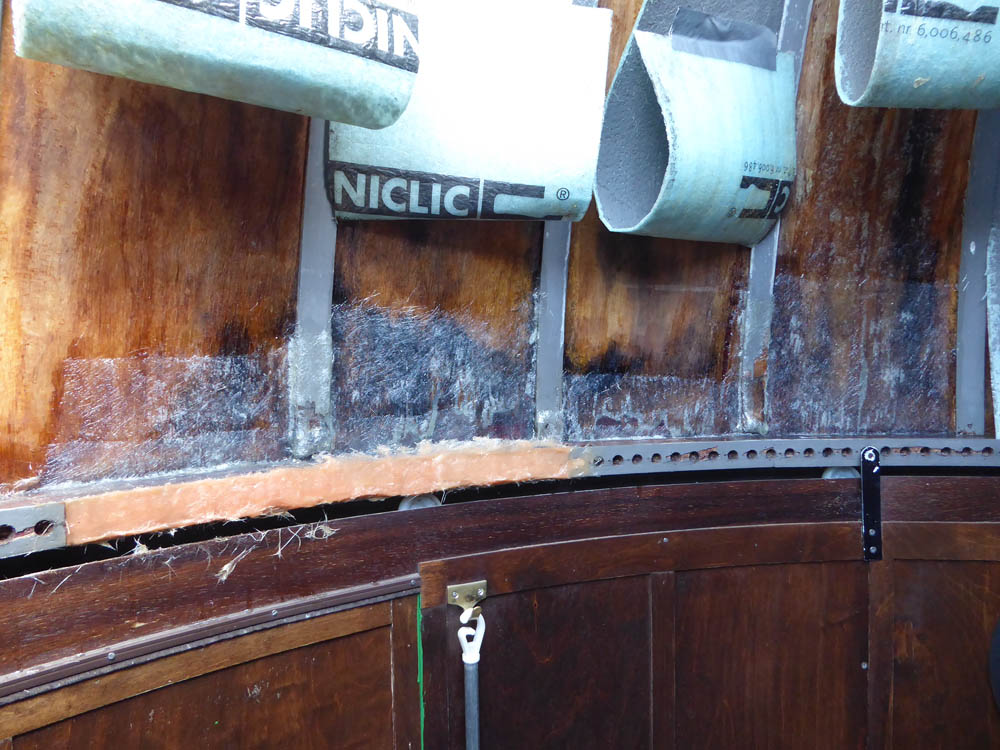
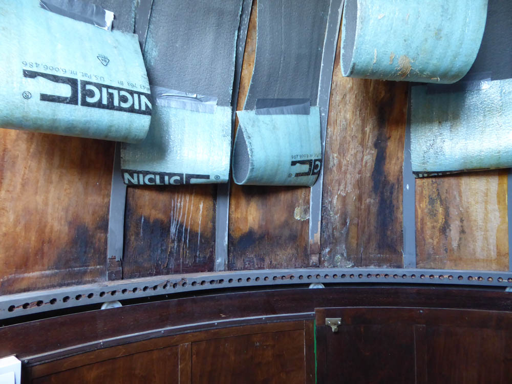
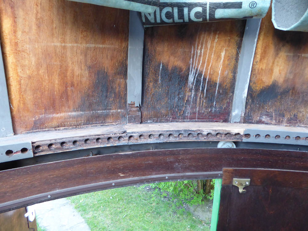
As I mentioned above, I discovered an area of quite extensive wet rot on a section of the rim. Caused almost certainly by ingress of rain due to paint cracking higher up on the dome. Because the inner surface of the plywood panelling is covered with thin plastic foam sheet, the moisture would have been trapped inside the plywood and migrated down with gravity. So much so that the top surface of the rim was actually wet! On discovering this I painted over the outside of the cracked area as best I could to seal most of it, and pulled away the plastic sheeting. The dehumidifier then did its job over a few weeks and dried everything out. It can't have helped that a previous dehumidifier had gradually decreased in efficiency over a period of time, so much so that in a week it collected less moisture than the replacement does in a day! But the dome walls were extensively damaged, and once the drive was fully operational I was unhappy with the stability of the damaged part of the rim which being a plywood strip had actually partly separated from the main section as can be seen in the photograph. |
|
|
So I resolved to strengthen the weakened areas with glass fibre mat and replace the plywood strip using glass fibre paste - this is essentially resin premixed with glass fibre and can be formed to shape. First of course I had to remove the damaged strip and prepare the top surface of the rim to allow the mat to get a good hold. Interestingly even after I had removed the damaged plywood strip, the drive still happily worked over that section!
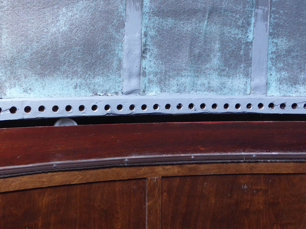
Then I applied mat over the top and face of the rim, covering the existing holes and also of course on the inner weakened surfaces of the dome plywood panels and cover strips. This meant that the load from the drive would be spread over a large area, and of course the damaged areas were considerably strengthened. The final operation was to apply the paste along the rim to bring it back up to profile. Not a perfect job, made a bit tricky because the paste set very quickly so could not be worked for long. But good enough. |
|
|
The next day, after giving the repair a chance to fully cure, it was a matter of final sanding to profile, re drilling the holes for the drive and giving it a coat of paint. Also of course the plastic sheeting was re fixed. Hopefully with a more comprehensive external repaint over the Summer this particular problem will not return. I still had the final jig for the hole drilling, which matched up perfectly with the old holes, and the drive runs happily over the repaired section. Disaster postponed, with any luck for a few more years. But see the foot of the main Observatory page re damage...... |
 |