Dew Heaters and Power panel (September 2000)
Dew can be a real nuisance when observing or imaging - because the instrument is pointing up at a clear sky, it cools below the air temperature, and if the humidity is relatively high dew can form on the optical surfaces. It is possible to calculate the dew point given the ambient temperature and relative humidity, indeed the three are interrelated, and I have written a small program, details on my Software page here.
There are numerous commercial dew heaters and controllers available, but it is relatively straightforward to make your own.
Here for SCT, here for EQ80, here for panel.
Alternative design for small heaters. Here.
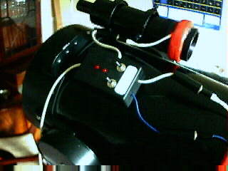
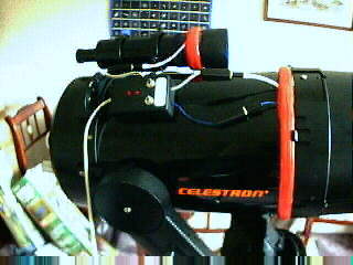
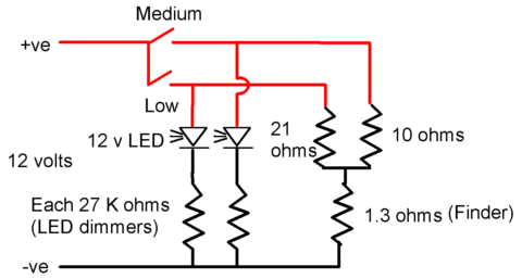
After losing most of a dark site session due to heavy dew, I decided to make a dew heater for my 8" SCT. (Another astronomer at the same session with heaters had no problems). After a bit of research, I decided to go for a wound coil using thin enamelled wire. I experimented with electronic control, but with limited success, so in the end went for a straightforward double coil with two switches, giving three settings - low, medium and high (with both switches on). The circuit is:
I linked the finder coil in series with the main heater coils to simplify the switching, keep the size of the finder coil to manageable proportions, and have the finder power follow the main 'scope power. The wire used was fine enamelled copper wire, 0.236 mm dia (34 SWG), giving a (measured) resistance of 0.41 ohms per metre. The theory is outlined at the bottom of the page, and the resistances I finally settled on give approximate output powers (watts at 12 volts) as follows:
Low--------------6.1------------0.4
Medium
---------11.3-----------1.5
High--------------15------------2.9
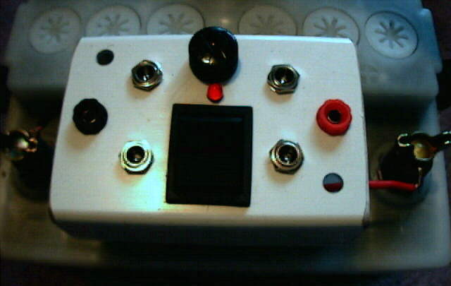
The light emitting diodes (LEDs) though having inbuilt resistance for 12 volt use were nevertheless excessively bright in the dark. So the dimmer resistances shown reduce the brightness to a reasonable level. Although not shown in the photos, I have replaced the red LED for the low power setting with a yellow one - just a fine touch so I can see at a glance which heater is on. I bought all the components from Maplin (UK). The cost (not including the tape, cardboard and resistors which were already in my parts box, but there's still loads of wire left on the 400 metre reel) was under £15.00, and I'm using a car battery for power.
The basic construction can of course be adapted for any telescope, you just need to determine the wattage required.
Method of construction
|
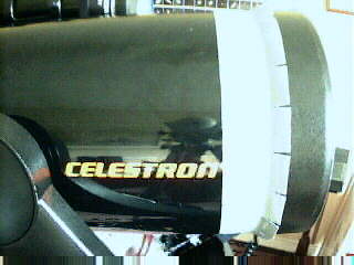
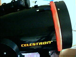
Slot a length of duct tape (about 3/4 metre for an 8" SCT) crossways about 1/3rd. of its width from each side at regular intervals, then wind it round the tube, sticky side outwards, just behind the lip of the corrector plate housing. |
|
|
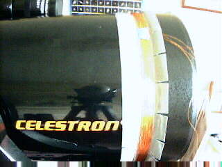
Wind the coils, keeping within the width of the uncut portion of the tape, leaving sufficient tail lengths for later termination. With the wire I used, I needed 73 turns for the low heat coil, and 33 turns for the medium heat coil. This would change for different thicknesses of wire. A test meter is essential! |
|
|
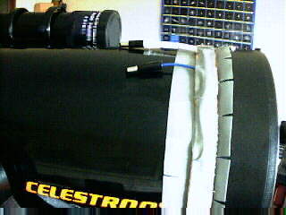
Wrap a single strip of corrugated cardboard around the coils, then connect the coils to the cables for linking to the control box, insulate the joints and secure the cables with tape. One connector carries the two inputs to the two coils, which are joined at one end, the other connector carries the single return. |
|
|
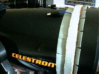
Wrap a second length of corrugated cardboard around the assembly. These cardboard strips provide protection and thermal insulation. |
|
|
Fold the slotted duct tape over the cardboard to contain the assembled components. |
|
|
Using electricians PVC tape, wrap a few turns to tidy up the edges and provide further protection. Note that this does not go underneath the coil, which remains in its assembly position at all times. |
|
|
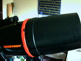
The Dew Cap lugs fit neatly over the assembled heater. |
|
|
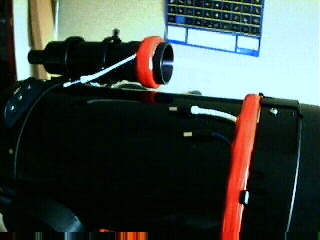
Using the same method, make the heater for the finder. |
|
|
A project box contains the switches, LED indicators and internal connections. I used 2.5 mm in-line jack plugs and line sockets (similar to those used for mains adaptor power supplies) for the connections. In later versions, I used panel mounting sockets (as used in the distribution panel below) instead of line sockets - a much neater job. |
|
|
Add a home made dew shield (a cut out aerosol can cap) to the finder, and all is ready! |
|
|
Following the same method as above, I also made a heater for my 80 mm short tube refractor. I wound the coil to 19.2 ohms, giving 7.5 watts at 12 volts. Because the coil is on top of the dew shield, and there is an air gap between the shield and the objective cell, I played safe on the power. Perhaps a bit high - the whole shield warms up. But I can always switch it off! I didn't make one for the finder, mainly because I use this telescope for general wide field viewing, and don't often use the finder. But 'in extremis' I can put in a low power eyepiece for the initial search. |
|
A little bit of theory
....-------------
The design of a resistive heater is based on Ohm's Law, Volts = Amps x Resistance
Normally written V = I R
Power = Volts x Amps or P = V I (combining the two equations we also get for power P = I²R and P = V²/R)
For the total of resistances in series (i.e. one after the other), simply add them together.
So for example the low power circuit resistance is R = Rfinder + Rlow. The current I flowing is V/R, the 'scope power is Rlow x I² and the finder power is Rfinder x I²
But for resistances in parallel, it's more complicated, since the total resistance is less than any of the paralleled resistances. The formula for this is:
Rtotal = 1/((1/R1) + (1/R2) + .... + (1/Rn)) for n resistances in parallel.
(HOWEVER if all the resistors are the same value the calculation is much easier. Simply divide the resistor value by the number of resistors in parallel. For example 10 x 620 ohm resistors in parallel gives a value of 620/10 = 62 ohms and 15 x 620 gives 620/15 = 41.33 ohms)
Anyway, in the case of the circuit used here, with both coils switched on, Rtotal=1/((1/Rlow) + (1/Rmedium))
The total current I = Battery voltage/(Rfinder +Rtotal), and because the coils are in parallel for the maximum power, then the main 'scope power is Rtotal x I². The finder power is again Rfinder x I²
I wrote a small spreadsheet in Microsoft Works format to juggle the figures for my circuit. It is available here, in self extracting .exe format - you must run it to extract the Works .wks format file. It's also available as a Microsoft Excel file here.
Heater for camera lenses and small telescopes
Although the fine wire system when properly installed is robust and works well, it is not transferable between instruments, and not so suitable for smaller instruments, in particular camera lenses where only a few watts of power are required - the amount of wire required to generate sufficient resistance is excessive, and high resistivity resistance wire is usually not insulated so again unsuitable for small heaters.
But a string of resistors in series, or a parallel 'ladder' works well. I favour the 'ladder' system - being based on flexible stranded wire it is more readily conformable to small diameters and can easily be used for different lenses. The method of construction is as follows (click on the thumbnails for larger pictures):
|
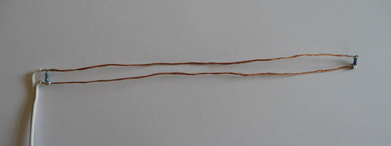
This particular heater was designed to give an output of approximately 2 1/2 watts at 12 volts. The maths is detailed above, in this case I used 10 x 620 ohm resistors, giving a total parallel resistance of 62 ohms and a power at 12 volts of 144/62 = 2.32 watts. The first stage is to strip the insulation from a suitable length of double stranded wire (loudspeaker wire is ideal), and solder a resistor to each end to stabilise the wire. The resistors are 0.6 watt metal film, and are small with a body length of only 6.5 mm (1/4") so the finished ladder easily sits on standard 1 inch wide Velcro ® tape. |
 |
|
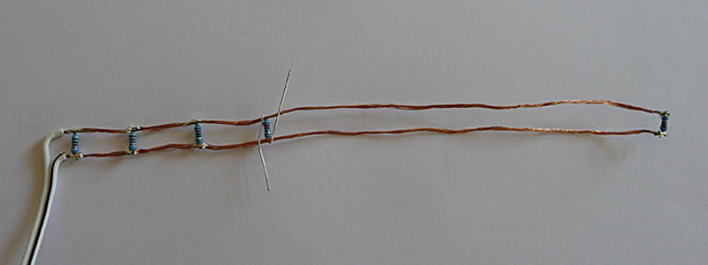
Space the resistors evenly along the ladder and make sure there are no sharp points protruding when trimming the resistor wire ends |
 |
|
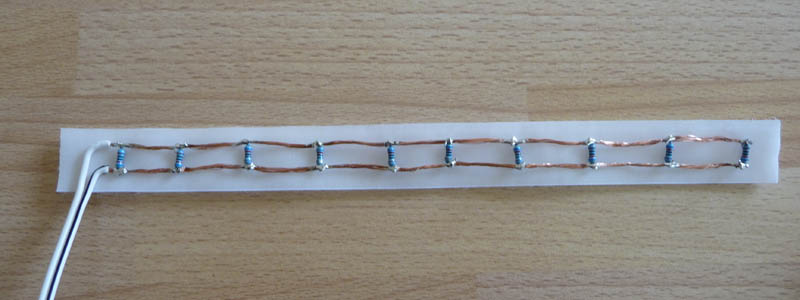
The finished ladder laid on the sticky side of self adhesive Velcro ® felt (the 'loop' part of hook and loop). Using the felt serves two purposes - being on the outside when installed it acts as insulation to retain the heat, and offers a surface for fixing as will be seen below. |
 |
|
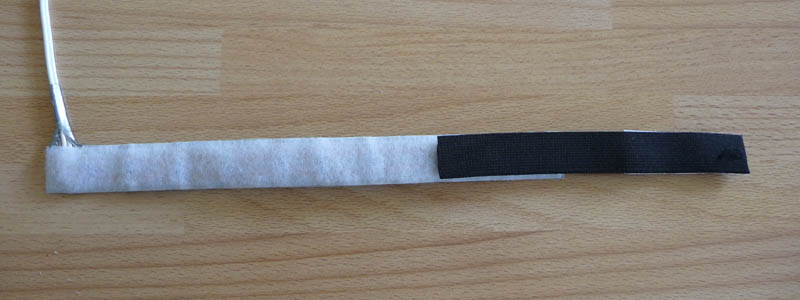
Then cover with duct tape. The sticky side of the tape forms a strong bond with the Velcro ® glue. If heavy duty, one layer will suffice, otherwise two layers for safety - we don't want the wire to rub through and short out on metal surfaces! Lay it on with one edge matching the edge away from the wire tail, then when trimmed leave enough to wrap round the wire as additional security. |
 |
|
A couple of pieces of self adhesive hook Velcro ® on elasticated fabric acts as a tensioning strap. Inside view. |
 |
|
Outside view. |
 |
|
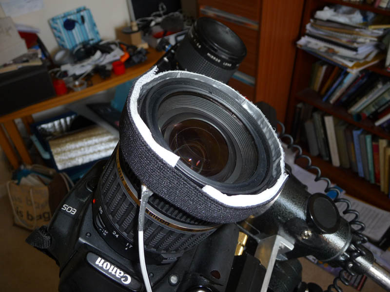
The finished heater fitted to a camera lens. You need to fix a suitable plug on the wire to suit your own control system. I just use an on/off switch, but of course the heater can be used with electronic controls . |
 |
|
Postscript. It is possible to make large heaters (for 8" or larger telescopes) using resistance wire laid on 2"wide Velcro ® and finished similarly to the above. Here is a schematic diagram for both the resistance ladder and resistance wire. Because resistance wire is normally not insulated it is important cleanly to separate the individual runs to avoid damaging short circuits. |
 |
|
Here is a schematic for a dual circuit heater system, switched to provide 3 heat settings. Obviously the heat required will depend on the size of the telescope. The LED's are there simply as indicators - might be an idea to use different colours. |
 |
|
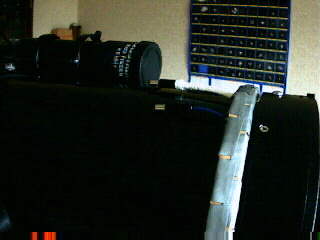
Because of the increasing number of power requirements, I built a distribution panel to fit on top of my car battery. It has four coaxial (5.5 mm o/d, 2.5 mm pin) sockets for use with lower current applications such as the dew heaters, electric focusser and future CCD cameras, and two banana plug sockets for higher currents e.g. my laptop. There is a main switch, a 10 amp fuse and a (dimmed) LED also on the panel. There were fixing holes conveniently placed on top of the battery, and I used a piece of rectangular PVC tube I had handy - a medium sized project box would do as well or better. |
|