
The building is composed of four frames, made from pressure-treated timber (readily available from Wickes) clad with WBP plywood. It stands on six paving slabs four of which had been in place for many years and were almost level. I laid two more. The frames will be bolted together with coach bolts.
Each frame is made in general from four pieces of 47×50 mm timber. The horizontal members are cut to the same length to ensure that the verticals are parallel; they are braced by gravel boards (150×19 mm boards) screwed and glued to them and also screwed to the uprights. The longer walls have an extra upright partly for a little extra strength but mainly to give more support to the cladding. The upper rails on the longer walls will be the runners for the wheels which are on 63 mm square plates, so these rails and the corresponding roof timbers are 47×75 mm, the wall timbers being cut to surround the verticals. All the horizontal timbers are fixed to the top of their gravel boards.
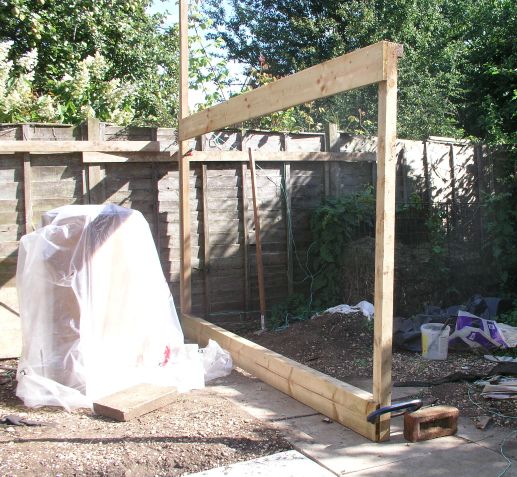
Because the paving slabs are not exactly level, the lower horizontal rails are positioned so that the gravel boards are at least 5 mm above the bottom of the posts. The highest slab is the one nearest the camera in the picture below so the first wall was constructed as follows.
The post nearest the camera in the pictures below was cut to length (1500 mm) and the lower horizontal attached to it at right angles in the workshop (garage). The far post was supported by a clamp to a board fixed to the fence posts and adjusted vertical using a spirit level. The other post with its horizontal beam was then placed in position, supported rather crudely with a G-clamp and a brick (actually this worked rather well), and adjusted until the horizontal bar was level when it was clamped to the upright before being screwed into place.
The upper beam was then put in position, supported initially be two G-clamps, carefully adjusted until the top of the beam was exactly level with the top of the 1500-mm post and then adjusted at the other end until exactly level. It was then screwed into place. The far post was then marked 118 mm above the top rail for cutting and a third upright cut to fit half way along the beams. The last post is secured to the upper gravel board by screws and to the lower beam by a T-plate.
 |
These pictures hopefully illustrate the way I am building the structure. In this picture you can see the first frame at the point where the horizontal beams are attached. The far post is temporarily secured to the fence. This view is from what will become the inside of the building. The gravel boards are attached on the inside, at the top because the roof will be guided by similar boards on the outside. The lower one is also on the inside as it will support the floor. This does create a slight problem for the end wall, which will be described below. |
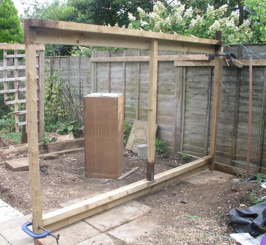 |
Here the side frame is complete. The far post has been cut to its final height and the extra post has been installed at the mid point. The rear post is higher than the near one so that the roof support will hit it to prevent the roof disappearing to next door. This is also the level where the sloping roof will start. |
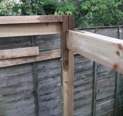 |
Because the gravel boards are on the inside of the side frames, the posts for the end section had to be cut away to accommodate them as shown here. When it came to the other end wall, I decided to pad the gap with extra pieces of board rather than cutting into the posts. This has the advantage that the end gable becomes smaller so that the roof will pass over it with more space to spare*. 29th August 2009 *I would like to claim that this was a conscious design feature, but the truth is it resulted from the idea that it made construction easier. |