The panels are supplied in standard ISO216 'A' series paper sizes, so in order fully to cover my 12" telescope I needed to purchase an A2 panel (approx 16" x 24"). I cut off an 8" strip from one end to give a 16" square panel, then assembled it using a hardboard backing. I used double sided sticky tape to keep the large panel flat on the hardboard.

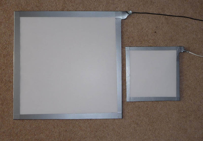
And here is the panel fixed to the board. Note the tongue on one corner to provide support for the wiring connector. The cut edge of the panel should be sealed (clear sellotape or similar) to prevent ingress of moisture. Although the luminescent coating looks pink when unpowered, the powered panel emits a pure white light.
The usable size because of the edge tape is approximately 14.5" x 14.5", but if I had used an oversize board, the full 16" x 16" would have been available. For my 12", the existing board is more than enough, and just that bit smaller!

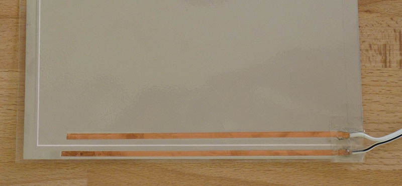
The cut off piece was 8" x 16", and had part of the electrode strips still in place.
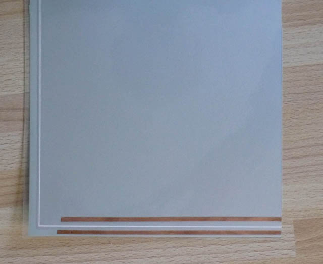
It seemed a shame to throw it away, so I carefully lifted one end of the electrode strips and soldered wires to them, with a matching plug for the power supply. (The panel is driven by high frequency alternating current at around 90 volts.) It worked! - the power unit for the big panel also drove the smaller panel (as expected). So I again trimmed it to give me an 8" x 8" panel (approx 6.5" x 6.5" when framed) suitable for my 127 mm and 80 mm refractors.
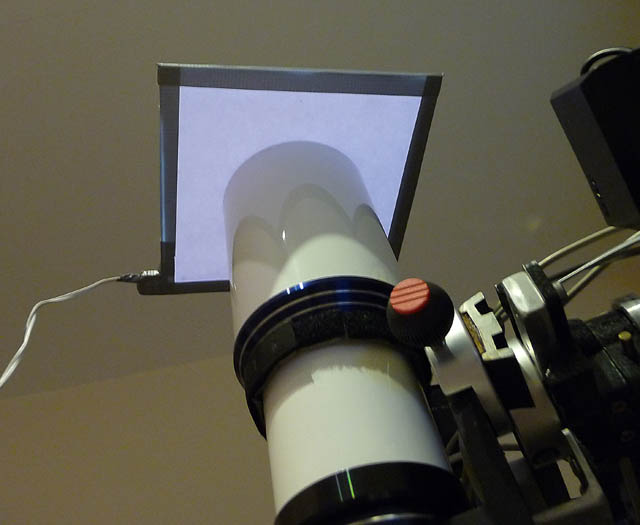
I found that the basic panel was too bright for my camera which is limited to 1/10th second minimum exposure time. But a few sheets of white paper brought it down to a sensible level. (Note : must be neutral white, not blue white like some computer paper). Then covered with translucent plastic sheet from a local art shop and taped round the edges. Job done - two for the price of one!
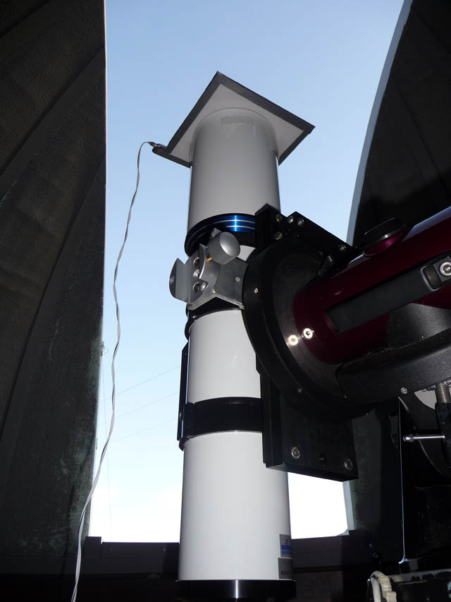
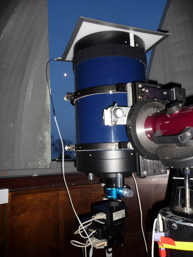
To use, the telescope is pointed vertically upwards, then the panel laid on top of the dew shield/telescope tube, and the necessary flats obtained. When not in use, of course the panels take up very little space. The power units ('inverters') run off the mains, but 12 volt powered inverters are also available.
These photos show the smaller panel on my 80 mm and 127 mm refractors, and the larger one on the 12" LX200ACF (yes, that's the Moon behind the LX200!)