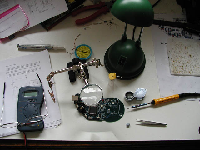
No specialist tools - just a table light, fine point soldering iron, a sheet of white laminate to work on so I didn't lose any tiny rice grain size components, extra strong (3.5 diopter) reading glasses from the local Pound Shop and a 'Helping Hands' from Maplin. Don't forget the fine point tweezers, absolutely essential. One or two soldering aids (see the Artemis site for a full list of must haves). And of course a small multimeter.
I have to say that when I first opened the kit, apart from being seriously impressed by the thought which had gone into the packing, labelling and instructions, I was totally terrified on seeing the size of some of the components and realised what I'd let myself in for. And every time I looked at the big, expensive 285 chip, I realised it was worth far more than its weight in gold. For a time I wished I'd never got involved, and was in no great hurry to start.
But as the first reports and minor modifications rolled in from the electronics wizards, I took heart and soldering iron and set to.
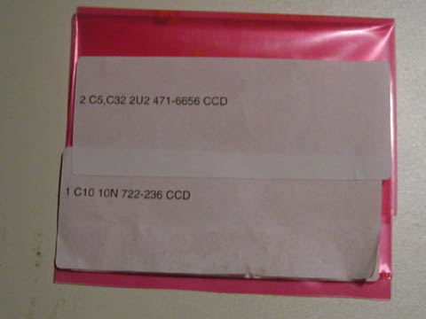
Most bags contained more than one item, but they were packed in such a way as to avoid any confusion with these tiny surface mount components, many of which were unlabelled.
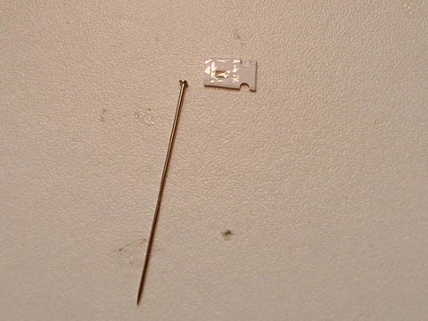
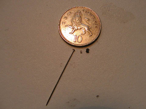
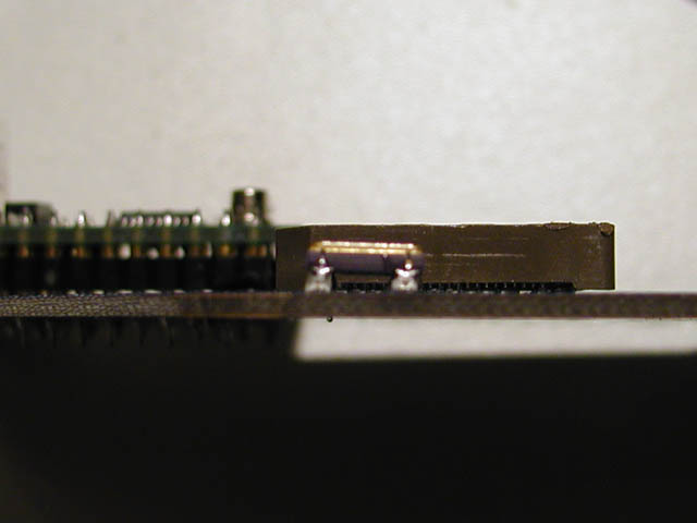
The pin in the photographs is a standard dressmaker's pin. the upper photo shows a resistor in its individual packing., the lower one shows it out of the pack, along with a 5-pin op-amp. The UK 10 pence piece lends scale.
Many of the components were miniscule as can be seen, and I had to proceed very carefully.
The first board to 'populate' with components was the Power Supply Unit (PSU). This supplies a variety of voltages to the main board, including a preset supply to the Peltier Cooler. Recommended levels for this were around 3.5 volts, so although it can be obtained from the main 12 volt supply, it was suggested that a separate 5 volt input be used if possible.
Most of the components on this board were reasonably large, and posed no great problem, although following reports and technical analyses from other builders, many of the surface mount capacitors were replaced with electrolytic versions.
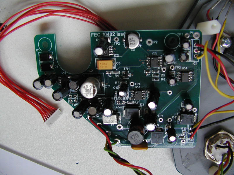
The cooling fan is powered from the PSU board, with a number of options. Direct from the 12 volt input supply, or from a 5 volt on-board supply.
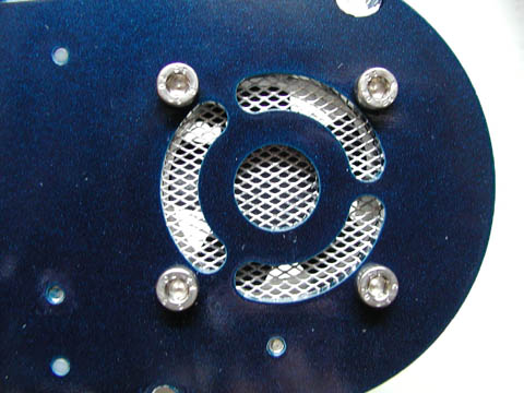
I decided to fit a grille to the cooling fan intake, and used a section of Aluminium mesh I had left over from a car fibreglass repair. To compensate for the reduction in air flow I wanted an in-between speed, so used a 47 ohm resistor to drop the voltage to around 8 volts from the main 12 volt input. The power leads for the main board and Peltier cooler are also taken from the back of the PSU board.

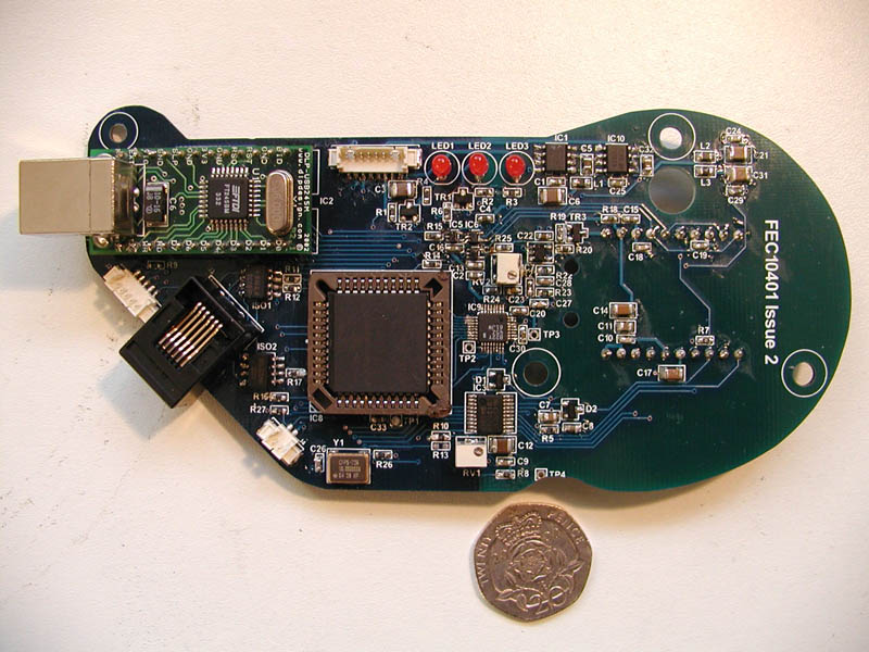
The Main board came next, and the construction was planned so that the most difficult components came later in the job, giving the builder practice on the easier items. An early problem was the oscillator crystal which was too big for the mounting pads, My solution was to build pillars of solder on the board. These gave enough space to get the soldering iron underneath the component and complete the fix.
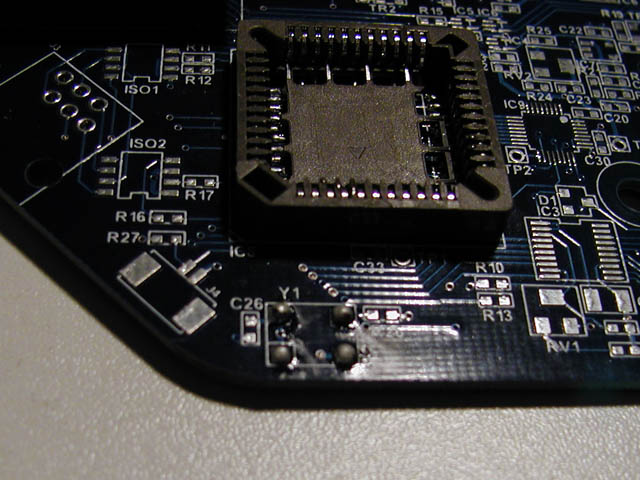
But eventually the board was populated although not without some scares!
A component with damaged legs (one of the opto-isolators), the tiny op-amps were very tricky, and IC9 was extremely difficult - I'm not surprised it was the very last component to install after lots of practice with the others. Although some of the soldering was tricky in the extreme, I was careful to test all joints, and also test for solder bridges.
This paid off - at various stages of the job there were diagnostic tests to carry out. They all proved correct first time - very heartening!
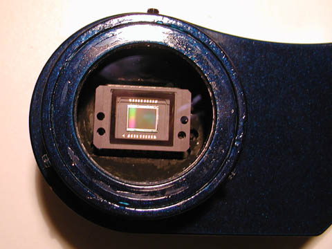
All that remained was to complete the assembly of the case and install the chip and Peltier cooler behind the front protective window. Then start testing the imaging capabilities. Bench tests with a camera lens went well, although at one point some of the software had to be revised (not by me!)
I painted the case a nice metallic blue, and it really looks the business!
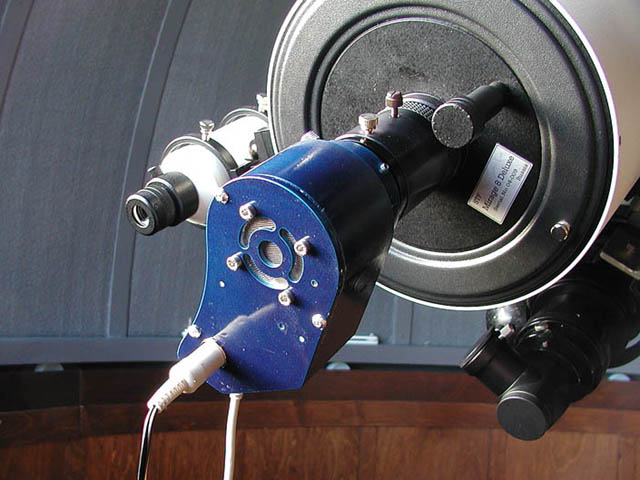
So then the camera could be installed on my telescope and imaging commence!
See the Artemis images page.